450 K/800 K High Temperature Interfaces
Principle of Operation
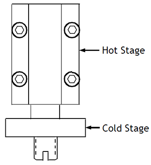
The 450/800 K Interface mounts on the cooler and contains an internal thermal switch which protects the cold end from excessive heat while experiments are carried out at elevated temperatures. The interface base which mounts on the cooler is referred to as the cold stage (Figure 1). The top portion of the interface, on which the sample mount is installed, is referred to as the hot stage. The thermal switch opens between hot stage temperatures of 200 K and 350 K, depending upon the cold stage temperature. At temperatures below 200 K, the thermal switch is engaged, resulting in minimum temperature difference between the sample and cold end minimum temperature. The switch is open at temperatures above 350 K, transferring minimum heat into the cold end at elevated sample temperatures. This allows the cold end to maintain a temperature below 350 K while the experiments at temperatures up to 450/800 K are performed on the sample.
NOTE: The cooler must always be in operation - even while the interface is above room temperature. This removes heat from the cooler and avoids overheating sensitive components inside the cooler.

Installation
Place an Indium gasket on the base of the 450/800 K interface and install the interface on the cold tip of the refrigerator. NOTE: Do not place the wrench on the hot stage of the interface during installation on the cold end! This could damage the interface. Use a ¾” open end wrench to secure the interface cold stage to the cold end.
Install the heater leads. 26 Ga Teflon coated copper wire may be used for heater leads. The leads should be heat sunk by making 4 to 6 wraps around the refrigerator first stage and loosely dressed to the second stage cylinder. Solder or mechanical crimp connections can be used to join the heater leads. The connection should be insulated with Teflon or fiberglass tubing.
Temperature sensors may be installed on the hot and cold stages of the interface using the #4-40 tapped holes. Hot stage sensor leads should be insulated with fiberglass tubing.
Check each electrical circuit for continuity, proper resistance, and electrical isolation. Heater resistance should be 47 to 50 Ohms.
Prepare to install the sample holder. Hold a ¾” open end wrench on the hot stage of the interface to avoid applying torque to the rest of the 450/800 K interface. NOTE: Do not torque the interface! Mount the sample holder on the interface. NOTE: The interface will support a maximum of 1.0 Kg (2.2 lb) or a moment of 0.33 N-m (3.0 in-lb) applied at the sample mount thread. A silver gasket may be used to improve thermal contact and achieve more uniform minimum temperature.
Repeat electrical tests after installing the radiation shield.
Instrumentation
Typically a type E thermocouple is used for the control sensor. An Au.07%Fe/chromel thermocouple and a platinum RTD are most often supplied “free-length” to measure the sample temperature. The freelength sensors are lashed to the cold tip for shipment and handling. Simply trace the loop in the freelength sensor leads and remove the thread or kapton tape retaining the loop so that the sensors can be moved in close proximity to the sample.
The E thermocouple control sensor is the best compromise between overall sensitivity over the entire temperature range and the ability to withstand 450/800 K. However, the sensitivity of the E thermocouple rolls off rapidly under 45 K, so it is not uncommon for the control temperature to read out at 20 K when the cryostat is really running much colder. The true temperature below 20 K can be read with the Au.07%Fe/chromel thermocouple which should be mounted close to the sample as described above. The Au.07%Fe/chromel thermocouple loses accuracy above 600 K. The platinum RTD is recommended for sample temperature readings above room temperature.
NOTE: The leads protruding from the platinum sensor are very fragile. The leads and junction to the copper conduction wires have been potted with ceramic paste to help protect them, but caution in handling the must be exercised to avoid breaking the sensor or leads.
Operation
A word on vacuum: If a mechanical pump is being used to provide insulating vacuum, the cold end should be valved off and isolated from the pump at cold end temperatures below 150 K to avoid back streaming oil into the experimental chamber. However, at elevated temperatures (particularly above 500 K) materials under test may outgas. It may be necessary to re-open the vacuum valve and actively pump to maintain an insulating vacuum level. Evidence of poor vacuum is a cooler than normal vacuum shroud that may condense water, higher than normal cold end temperature, and higher than normal heater power required to maintain temperature. If the vacuum valve is opened, care must be taken to close the valve again when the sample is re-cooled to avoid streaming oil into the experimental chamber.
Typical warm-up characteristics of the 450/800 K interface are shown in Figure 2. The slope of the warm up curve in Figure 2 is higher below 200 K because the thermal switch is engaged. Above this point the thermal switch is open and the slope is negative until the difference in temperature becomes significant enough to increase the heat transfer once again. The cool down curve does not follow the same path at the warm up curve because the thermal switch is a passive mechanical device which is dependent upon both the hot and cold stage temperatures.
Warm up time from 11 K to 800 K is approximately 1 hour. Cool down from 800 K to 12 K is approximately 2 hours with a DE-202 or 80 minutes with a DE-204.
